phased.UCA
Uniform circular array
Description
The phased.UCA
System object™ creates a uniform circular array (UCA). A UCA is
formed from identical sensor elements equally spaced around a circle.
To compute the response for the array for specified directions:
Create the
phased.UCAobject and set its properties.Call the object with arguments, as if it were a function.
To learn more about how System objects work, see What Are System Objects?
Creation
Syntax
Description
sUCA = phased.UCA creates a uniform circular array (UCA)
System object, sUCA, consisting of five identical isotropic
antenna elements,phased.IsotropicAntennaElement. The
elements are equally spaced around a circle of radius 0.5 meters.
sUCA = phased.UCA(
creates a System object, Name=Value)sUCA, with each specified property Name set
to the specified Value. You can specify additional name-value pair arguments in
any order as
(Name1=Value1,...,NameN=ValueN).
For example, to specify array normal direction, set
ArrayNormal="x"
sUCA = phased.UCA(
creates a UCA System object, N,R)sUCA, with the
NumElements property set to N and
the Radius property set to R. This
syntax creates a UCA consisting of isotropic antenna elements, phased.IsotropicAntennaElement.
sUCA = phased.UCA(
creates a UCA System object, N,R,Name=Value)sUCA, with the
NumElements property set to N, the
Radius property set to R, and
other specified property Names set to the specified Values.
Properties
Usage
Syntax
Description
RESP = sUCA(FREQ,ANG)RESP, of the array elements, at
operating frequencies specified in FREQ and directions
specified in ANG.
Note
The object performs an initialization the first time the object is executed. This
initialization locks nontunable properties
and input specifications, such as dimensions, complexity, and data type of the input data.
If you change a nontunable property or an input specification, the System object issues an error. To change nontunable properties or inputs, you must first
call the release method to unlock the object.
Input Arguments
Output Arguments
Object Functions
To use an object function, specify the
System object as the first input argument. For
example, to release system resources of a System object named obj, use
this syntax:
release(obj)
Examples
Create an 11-element uniform circular array (UCA) having a 1.5 m radius and operating at 500 MHz. The array consists of short-dipole antenna elements. First, display the vertical component of the response at 45 degrees azimuth and 0 degrees elevation. Then plot the azimuth and elevation directivities.
antenna = phased.ShortDipoleAntennaElement(...
    FrequencyRange=[50e6,1000e6], ...
    AxisDirection="Z");
array = phased.UCA(NumElements=11,Radius=1.5,Element=antenna);
fc = 500e6;
ang = [45;0];
resp = array(fc,ang);
disp(resp.V)
   -1.2247
   -1.2247
   -1.2247
   -1.2247
   -1.2247
   -1.2247
   -1.2247
   -1.2247
   -1.2247
   -1.2247
   -1.2247
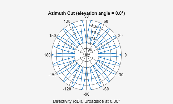
Display the azimuth directivity pattern at 500 MHz for azimuth angles between -180 and 180 degrees.
c = physconst('LightSpeed');
pattern(array,fc,[-180:180],0,Type="directivity",PropagationSpeed=c)
Display the elevation directivity pattern at 500 MHz for elevation angles between -90 and 90 degrees.
pattern(array,fc,[0],[-90:90],Type="directivity",PropagationSpeed=c)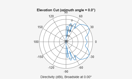
Algorithms
A UCA is formed from N identical sensor elements equally spaced around a circle of radius R. The circle lies in the xy-plane of the local coordinate system whose origin lies at the center of the circle. The positions of the elements are defined with respect to the local array coordinate system. The circular array lies in the xy-plane of the coordinate system. The normal to the UCA plane lies along the positive z-axis. The elements are oriented so that their main response directions (normals) point radially outward in the xy-plane.

If the number of elements of the array is odd, the middle element lies on the x-axis. If the number of elements is even, the midpoint between the two middle elements lies on the x-axis. For an array of N elements, the azimuth angle of the position of the nth element is given by
The azimuth angle is defined as the angle, in the xy-plane, from the x-axis toward the y-axis. The elevation angle is defined as the angle from the xy-plane toward the z-axis. The angular distance between any two adjacent elements is 360/N degrees. Azimuth angle values are in degrees. Elevation angles for all array elements are zero.
References
[1] Brookner, E., ed. Radar Technology. Lexington, MA: LexBook, 1996.
[2] Van Trees, H. Optimum Array Processing. New York: Wiley-Interscience, 2002, pp. 274–304.
Extended Capabilities
Version History
Introduced in R2015a
See Also
phased.URA | phased.ULA | phased.ConformalArray | phased.CosineAntennaElement | phased.CrossedDipoleAntennaElement | phased.CustomAntennaElement | phased.IsotropicAntennaElement | phased.ShortDipoleAntennaElement | phased.CustomMicrophoneElement | phased.OmnidirectionalMicrophoneElement | sidelobelevel