Main Content

Network Coupler (Capacitor)

Split network at an electrical connection by replacing a capacitor

Since R2022a

  • Network Coupler (Capacitor) block

Libraries:
Simscape / Utilities / Network Couplers

Description

The Network Coupler (Capacitor) block uses a capacitor connected to an electrical reference to break a network connection. This block can be useful for breaking the return path for a DC-DC connection. However, it is not that useful for representing a typical stray capacitance to ground because the resulting time constant would be very fast, requiring unrealistic sample times. The capacitance value that you specify typically needs to be of the order of a few hundred microfarads. For more information, see Using the Derived Values to Estimate Block Parameters.

Both of the port interfaces of the Network Coupler (Capacitor) block are implemented as voltage sources. Therefore, you cannot connect this block to a voltage loop, such as a set of series-connected voltage sources and capacitors, because this would cause an Index-2 topology (for more information, see Avoiding Numerical Simulation Issues).

To facilitate working with models that contain arrays of electrical nodes or three-phase connection, the Port 1 Interface and Port 2 Interface subsystems contain custom blocks, such as Controlled Voltage Source or Current Sensor. These custom blocks are based on the equivalent Foundation library blocks but are modified to support vectorized and three-phase electrical nodes. The source files for these custom blocks are located in the following namespace:

matlabroot/toolbox/physmod/simscape/library/m/+foundation/+internal/+couplers/+electrical

where matlabroot is the MATLAB® root directory on your machine, as returned by entering

matlabroot

at the MATLAB command prompt. The namespace contains source files for voltage and current sources and sensors, as well as a resistor and an electrical reference with array and three-phase support. You can use these blocks to customize your network coupler configuration.

Working with the Block on the Model Canvas

When you add the block to your model and double-click it, the Network Coupler (Capacitor) subsystem opens.

Network Coupler (Capacitor) subsystem diagram

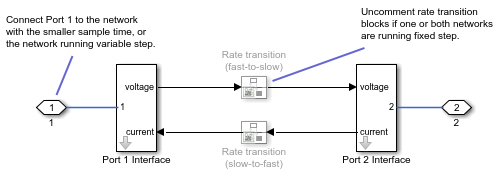
The Port 1 Interface block contains the dynamics that break the algebraic loop. Double-click this block to set all of the Network Coupler (Capacitor) subsystem parameters and view the derived values.

The rate transition blocks are, by default, commented through. Uncomment them if at least one of the coupled networks is running fixed step.

Using the Derived Values to Estimate Block Parameters

On the Analysis tab of the Port 1 Interface block dialog box, the Derived values section contains a list of recommended values that you can use when specifying block parameters. For example, use the Recommended max discrete sample time (s) derived value to verify that your Port 1 network discrete sample time (s) and Port 2 network discrete sample time (s) parameter values are within acceptable limits.

The derived values list is based on the chosen block configuration.

If both networks are running variable step, then the Analysis tab is empty, and there are no restrictions on the capacitance value you specify.

If one or both networks are running fixed step, then the Analysis tab provides assistance on selecting a suitable capacitance value, by asking you for an approximate resistance value for the connected networks. If the resistances of the two networks differ, provide the lower value. The Update button then provides a maximum recommended discrete sample time to use.

Ports

Conserving

expand all

If one of the coupled networks is running variable step, connect it to port 1 of the Network Coupler (Capacitor) block. If both networks are running fixed step, connect this port to the network with the smaller sample time. If both networks are running variable step, or fixed step with the same step size, then the block polarity does not matter.

If one of the coupled networks is running variable step, connect port 2 of the Network Coupler (Capacitor) block to the fixed-step network. If both networks are running fixed step, connect this port to the network with the larger sample time.

Parameters

expand all

Main

Select this check box when breaking connections between three-phase electrical ports. Because the top-level subsystem is unmasked, you need to select this check box both for Port 1 Interface and Port 2 Interface blocks. Selecting this check box disables the Electrical node array size parameter because ports 1 and 2 become three-phase electrical ports.

Specify the size of the electrical node array connected to the two electrical ports, 1 and 2. Because the top-level subsystem is unmasked, you need to set this parameter to the same value both for Port 1 Interface and Port 2 Interface blocks.

If you are breaking a regular electrical connection, leave the default value of 1 unchanged.

Dependencies

To enable this parameter, clear the Use three-phase electrical connections check box.

Specify the inductance value. Use the Capacitance parameter value from the Capacitor block being replaced, converting it to F, if necessary.

Select how the coupled networks are sampled:

  • Variable step at ports 1 and 2 — Both networks are variable-step.

  • Variable step at port 1 and fixed step at port 2 — Network 1 is variable-step and Network 2 is fixed-step.

  • Fixed step both ports with common sample time — Both networks are fixed-step, with the same step size.

  • Fixed step both ports with faster sampling at port 1 — Both networks are fixed-step, with different step sizes.

Specify sample time for Network 1, in seconds.

Dependencies

To enable this parameter, set the Sampling type parameter to Fixed step both ports with common sample time or Fixed step both ports with faster sampling at port 1.

Specify sample time for Network 2, in seconds.

Dependencies

To enable this parameter, set the Sampling type parameter to Variable step at port 1 and fixed step at port 2 or Fixed step both ports with faster sampling at port 1.

Select this check box to enable the prediction (discrete->continuous) algorithm. For more information, see Prediction and Smoothing.

Dependencies

To display this option, set the Sampling type parameter to Variable step at port 1 and fixed step at port 2.

Select this check box to enable the smoothing (continuous->discrete) algorithm. For more information, see Prediction and Smoothing.

Dependencies

To display this option, set the Sampling type parameter to Variable step at port 1 and fixed step at port 2.

Specify time constant, in seconds, for the first-order filter that the smoothing algorithm uses to remove unwanted high-frequency information.

Dependencies

To enable this parameter, select the Use smoothing when connecting variable step to fixed step check box.

Select this check box to enable the prediction (slow->fast) algorithm. For more information, see Prediction and Smoothing.

Dependencies

To display this option, set the Sampling type parameter to Fixed step both ports with faster sampling at port 1.

Select this check box to enable the smoothing (fast->slow) algorithm. For more information, see Prediction and Smoothing.

Dependencies

To display this option, set the Sampling type parameter to Fixed step both ports with faster sampling at port 1.

The smoothing algorithm works by averaging the last N samples. You specify N by using this parameter.

Dependencies

To enable this parameter, select the Use smoothing when connecting fast to slow sample times check box.

Analysis

Specify approximate resistance of the connected network, in ohm. If the resistances of the two networks differ, provide the lower value.

Dependencies

To enable this parameter, set the Sampling type parameter to Variable step at port 1 and fixed step at port 2, Fixed step both ports with common sample time, or Fixed step both ports with faster sampling at port 1.

For information on how to use the Derived values section, see Using the Derived Values to Estimate Block Parameters.

Initial Conditions

Specify initial condition for the voltage across the capacitor, in V.

Extended Capabilities

C/C++ Code Generation
Generate C and C++ code using Simulink® Coder™.

Version History

Introduced in R2022a

expand all