Validate Tuned Control System
When you tune a control system using systune or Control System
Tuner, you must validate the results of tuning. The tuning results provide numeric and
graphical indications of how well your tuning goals are satisfied. (See Interpret Numeric Tuning Results and Visualize Tuning Goals.) Often, you want to examine other
system responses using the tuned controller parameters. If you are tuning a Simulink® model, you must also validate the tuned controller against the full nonlinear
system. At the command line and in Control System Tuner, there are several tools to
help you validate the tuned control system.
Extract and Plot System Responses
In addition to the system responses corresponding to your tuning goals (see Visualize Tuning Goals), you can evaluate the tuned system performance by plotting other system responses. For instance, evaluate reference tracking or overshoot performance by plotting the step response of transfer function from the reference input to the controlled output. Or, evaluate stability margins by examining an open-loop transfer function. You can extract any transfer function you need for analysis from the tuned model of your control system.
Extract System Responses at the Command Line
The tuning tools include analysis functions that let you extract responses from your tuned control system.
For generalized state-space (genss) models,
use:
For an slTuner interface, use:
In either case, the extracted responses are represented by state-space
(ss) models. You can analyze these models using
commands such as step, bode, sigma,
or margin.
For instance, suppose that you are tuning the control system
of the example Multiloop Control of a Helicopter. You have created
an slTuner interface ST0 for
the Simulink model. You have also specified tuning goals TrackReq, MarginReq1, MarginReq2,
and PoleReq. You tune the control system using systune.
AllReqs = [TrackReq,MarginReq1,MarginReq2,PoleReq];
ST1 = systune(ST0,AllReqs);
Final: Soft = 1.12, Hard = -Inf, Iterations = 72
Suppose also that ST0 has analysis points
that include signals named theta-ref, theta, phi-ref,
and phi. Use getIOTransfer to
extract the tuned transfer functions from theta-ref and phi-ref to theta and phi.
T1 = getIOTransfer(ST1,{'theta-ref','phi-ref'},{'theta','phi'});
step(T1,5)
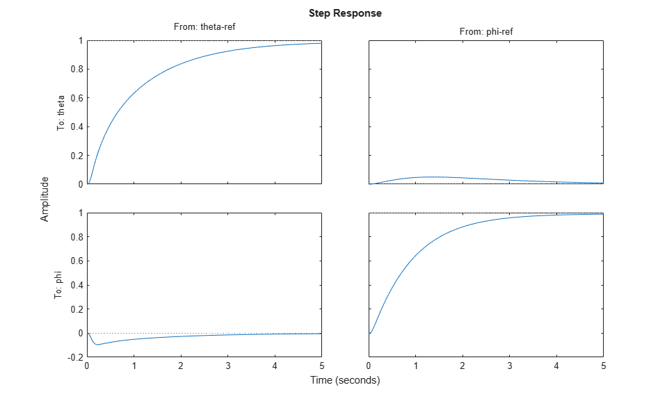
The step plot shows that the extracted transfer function is the 2-input, 2-output response from the specified reference inputs to the specified outputs.
For an example that shows how to extract responses from a tuned genss model,
see Extract Responses from Tuned MATLAB Model at the Command Line.
For additional examples, see Validating Results.
System Responses in Control System Tuner
For information about extracting and plotting system responses in Control System Tuner, see Create Response Plots in Control System Tuner.
Validate Design in Simulink Model
When you tune a Simulink model, the software evaluates
tuning goals for a linearization of the model. Similarly, analysis
commands such as getIOTransfer extract linearized
system responses. Therefore, you must validate the tuned controller
parameters by simulating the full nonlinear model with the tuned controller
parameters, even if the tuned linear system meets all your design
requirements. To do so, write the tuned parameter values to the model.
Tip
If you tune the Simulink model at an operating point other than the model initial condition, initialize the model at the same operating point before validating the tuned controller parameters. See Simulate Simulink Model at Specific Operating Point.
Write Parameters at the Command Line
To write tuned block values from a tuned slTuner interface
to the corresponding Simulink model, use the writeBlockValue command. For example,
suppose ST1 is the tuned slTuner interface
returned by systune. The following command writes
the tuned parameters from ST1 to the associated Simulink model.
writeBlockValue(ST1)
Simulate the Simulink model to evaluate system performance with the tuned parameter values.
Write Parameters in Control System Tuner
To write tuned block parameters to a Simulink model, in the Control System tab, click
![]() Update Blocks.
Update Blocks.

Control System Tuner transfers the current values of the tuned block parameters to the corresponding blocks in the Simulink model. Simulate the model to evaluate system performance using the tuned parameter values.
To update Simulink model with parameter values from a previous design stored in Control
System Tuner, click ![]() Retrieve and select the stored design that you want to make the
current design. Then click
Retrieve and select the stored design that you want to make the
current design. Then click ![]() Update Blocks.
Update Blocks.