Getting Started with vHIL Simulation for Infineon AURIX TC4x Microcontrollers
This example shows how to use SoC Blockset™ Support Package for Infineon® AURIX™ Microcontrollers for virtual hardware-in-the-loop (vHIL) simulation using Synopsis® Virtualizer Development Kit (VDK).
Introduction
vHIL simulation is especially useful when testing your control algorithm on the real-world physical system is costly or dangerous. This simulation is widely used in the automotive, aerospace, defense, industrial automation, and machinery industries to test embedded designs. Virtual prototyping (VP) is integrated into the VDK from Synopsys® and this example shows you how to generate a Simulink model that co-simulates with the VDK. For more information on VP, refer to Run Model on Virtual Prototyping (VP).
In this example, you will learn how to periodically turn an LED on and off in different patterns in model-in-the-loop (MIL), code generation, and vHIL workflows.
Prerequisites
Complete the Getting Started with SoC Blockset Support Package for Infineon AURIX Microcontrollers example.
Required Hardware
Infineon AURIX TC49A
Micro-USB cable
Required Software
Synopsys® Virtualizer Development Kit (VDK)
Available Model
The example includes the tc4x_8ledsBlinky_vhil model.

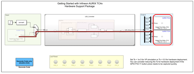
The model comprises of four modules:
Input: This subsystem inputs source signals to Variant Subsystem through Variant Source block, which activates the codegen or sim options during simulation. The sim option enables MIL and vHIL workflows and inputs signals from the Simulink blocks. The hardware board's GPIO pins provide the input signals for the code generation.
Variant Subsystem: This subsystem consists of the variant choices mil(MIL and Codegen) and vhil(vHIL). You can select the active variant during model execution. The algorithm in this subsystem generates two patterns and the switch P33.11 connected to the board controls the pattern. When the switch detects a leading edge, the output of the D Flip-Flop block toggles between 0 and 1. The model generates Pattern 1, when the D Flip-Flop outputs 0 and Pattern 2 when it outputs 1.
Pattern 1: LEDs blink from right to left and vice versa.
Pattern 2: LEDs on the alternate pins blink.
Output: This subsystem receives information about LED blinking patterns through a variant sink, which activates the codegen or sim options during simulation. The sim option enables MIL and vHIL workflows, where the subsystem outputs the signals to the LED Panel block. The codegen option directs the output signals to the GPIO pins in the hardware board.
LED Panel: In MIL and vHIL simulations, you can observe two different blinking patterns on the LED Panel block. For code generation workflow, you can observe two different blinking patterns of eight LEDs connected to the board (P33.0, P33.1, P33.4, P33.5, P13.0, P13.1, P13.2, and P13.3).
Configure the Model
1. Open the tc4x_8ledsBlinky_vhil model.
2. Press Ctrl+E to open the Configuration Parameters dialog box. Click Hardware Implementation in the left pane and set Hardware board to Infineon AURIX™ TC4x - TriBoards.
3. Enter the following command in the MATLAB® prompt:
For VP simulation:
Ts = 1e-3
For hardware deployment:
Ts = 1
4. Click OK.
MIL Simulation
1. Open the tc4x_8ledsBlinky_vhil model.
2. Right-click Variant Subsystem to open the options. Click Variant > Label Mode Active Choice > mil(MIL and Codegen).
3. Click Run on the Simulation tab to simulate the model. This figure depicts the simulation path in the MIL mode.

4. Observe two different blinking patterns in the LED Panel subsystem.
Generate Code for Microcontroller
1. Open the tc4x_8ledsBlinky_vhil model.
2. Right-click Variant Subsystem to open the options. Click Variant > Label Mode Active Choice > mil(MIL and Codegen).
3. Go to Hardware > Deploy and click Build, Deploy & Start. to create the generated code as an executable and linkable format (ELF) file.
This figure depicts the simulation path in code generation.
vHIL Simulation
1. Open the tc4x_8ledsBlinky_vhil model.
2. The available model in this example is preconfigured and you can change the setup by following these steps:
Connect the interface blocks from the Simulink to the VDK by running the python script
\SLS\windows\thirdparty_integrations\simulink\vsi_setup_virtualizer.m, which is part of the VP installation process.
The script adds
virtualizer_blk_libblocks to the path.

This example includes
BlinkyLED-vHILfolder, which contains the required files for vHIL simulation. You can examine theConnect_Simulink.pyscript in this folder to understand the connections between Simulink signals and VDK pins.
3. Launch the Virtualizer Studio (VDK) from Simulink diagnostic viewer. Go to File > Import.

4. In the import window, click next and import the VP configuration file (BlinkyLED-vHIL.vpcfg from BlinkyLED-vHIL folder) shipped with this example.

5. From the Images tab in the VP Configuration file, go to TriCore and click browse to provide the ELF file which was created in step 3 of the Generate Code for Microcontroller section (code generation workflow).
6. Click Run to hit the Initial crunch and click play.
7. Go to the Simulink model, right-click on the Variant Subsystem to open the options. Click Variant > Label Mode Active Choice > vhil(vHIL).
8. Click Run on the Simulation tab to initiate vHIL simulation of the model. The Virtual Prototyping (VP) and Simulink® run in locksteps waiting on each other.
This example illustrates co-simulation of the Simulink model with Virtualizer Development Kit. The algorithm generating the LED pattern runs on the VDK, where as the input and visualization outputs run in Simulink.
This figure shows the simulation path in vHIL mode.

9. Click Analysis tab of the BlinkyLED-vHIL.vpcfg file and select the GPIO pins, where you want to observe the signals.

10. Click the Charts tab to observe the signals at the GPIO pins.

You can observe LED blinking patterns on the GPIO pins of the hardware board, similar to those on the LED Panel subsystem in the Simulink model.
Example Demo
See Also
You can also select a web site from the following list:
Americas
- América Latina (Español)
- Canada (English)
- United States (English)
Europe
- Belgium (English)
- Denmark (English)
- Deutschland (Deutsch)
- España (Español)
- Finland (English)
- France (Français)
- Ireland (English)
- Italia (Italiano)
- Luxembourg (English)
- Netherlands (English)
- Norway (English)
- Österreich (Deutsch)
- Portugal (English)
- Sweden (English)
- Switzerland
- United Kingdom (English)