Solar Cell
Photovoltaic solar cell

Libraries:
Simscape /
Electrical /
Sources
Description
The Solar Cell block represents a solar cell current source.
The solar cell model includes the following components:
Solar-Induced Current
The block represents a single solar cell as a resistance Rs that is connected in series with a parallel combination of the following elements:
Current source
Two exponential diodes
Parallel resistor Rp
The following illustration shows the equivalent circuit diagram:

The output current I is
where:
Iph is the solar-induced current:
where:
Ir is the irradiance (light intensity), in W/m2, falling on the cell.
Iph0 is the measured solar-generated current for the irradiance Ir0.
Is is the saturation current of the first diode.
Is2 is the saturation current of the second diode.
Vt is the thermal voltage, kT/q, where:
k is the Boltzmann constant.
T is the Device simulation temperature parameter value.
q is the elementary charge on an electron.
N is the quality factor (diode emission coefficient) of the first diode.
N2 is the quality factor (diode emission coefficient) of the second diode.
V is the voltage across the solar cell electrical ports.
The quality factor varies for amorphous cells, and is typically
2 for polycrystalline cells.
The block lets you choose between two models:
An 8-parameter model where the preceding equation describes the output current
A 5-parameter model that applies the following simplifying assumptions to the preceding equation:
The saturation current of the second diode is zero.
The impedance of the parallel resistor is infinite.
If you choose the 5-parameter model, you can parameterize this block in terms of the preceding equivalent circuit model parameters or in terms of the short-circuit current and open-circuit voltage the block uses to derive these parameters.
All models adjust the block resistance and current parameters as a function of temperature.
You can model any number of solar cells connected in series using a single Solar Cell block by setting the parameter Number of series-connected cells per string to a value larger than 1. Internally the block still simulates only the equations for a single solar cell, but scales up the output voltage according to the number of cells. This results in a more efficient simulation than if equations for each cell were simulated individually.
Temperature Dependence
Several solar cell parameters depend on temperature. The solar cell temperature is specified by the Device simulation temperature parameter value.
The block provides the following relationship between the solar-induced current Iph and the solar cell temperature T:
where:
TIPH1 is the First order temperature coefficient for Iph, TIPH1 parameter value.
Tmeas is the Measurement temperature parameter value.
The block provides the following relationship between the saturation current of the first diode Is and the solar cell temperature T:
where TXIS1 is the Temperature exponent for Is, TXIS1 parameter value.
The block provides the following relationship between the saturation current of the second diode Is2 and the solar cell temperature T:
where TXIS2 is the Temperature exponent for Is2, TXIS2 parameter value.
The block provides the following relationship between the series resistance Rs and the solar cell temperature T:
where TRS1 is the Temperature exponent for Rs, TRS1 parameter value.
The block provides the following relationship between the parallel resistance Rp and the solar cell temperature T:
where TRP1 is the Temperature exponent for Rp, TRP1 parameter value.
Predefined Parameterization
There are multiple available built-in parameterizations for the Solar Cell block.
This pre-parameterization data allows you to set up the block to represent components by specific suppliers. The parameterizations of these solar cell modules match the manufacturer data sheets. To load a predefined parameterization, double-click the Solar Cell block, click the <click to select> hyperlink of the Selected part parameter and, in the Block Parameterization Manager window, select the part you want to use from the list of available components.
Note
The predefined parameterizations of Simscape™ components use available data sources for the parameter values. Engineering judgment and simplifying assumptions are used to fill in for missing data. As a result, expect deviations between simulated and actual physical behavior. To ensure accuracy, validate the simulated behavior against experimental data and refine component models as necessary.
For more information about pre-parameterization and for a list of the available components, see Simscape Electrical Part Collection.
Thermal Port
You can expose the thermal port to model the effects of generated heat and device temperature. To expose the thermal port, set the Modeling option parameter to either:
No thermal port— The block does not contain a thermal port and does not simulate heat generation in the device.Show thermal port— The block contains a thermal port that allows you to model the heat that conduction losses generate. For numerical efficiency, the thermal state does not affect the electrical behavior of the block.
For more information on using thermal ports and on the Thermal Port parameters, see Simulating Thermal Effects in Semiconductors.
The thermal port model, shown in the following illustration, represents just the thermal mass of the device. The thermal mass is directly connected to the component thermal port H. An internal Ideal Heat Flow Source block supplies a heat flow to the port and thermal mass. This heat flow represents the internally generated heat.

The internally generated heat in the solar cell is calculated according to the equivalent circuit diagram, shown at the beginning of the reference page, in the Solar-Induced Current section. It is the sum of the i2 · R losses for each of the resistors plus the losses in each of the diodes.
The internally generated heat due to electrical losses is a separate heating effect to that of the solar irradiation. To model thermal heating due to solar irradiation, you must account for it separately in your model and add the heat flow to the physical node connected to the solar cell thermal port.
Generate Derived Data Sheet
Since R2024b
You can generate a derived data sheet for the Solar Cell block that contains summary tables and characteristic plots similar to those that device manufacturers provide in their data sheets. A built-in MATLAB® script calculates the block-level characteristics based on the parameter values in your model. Use derived data sheets to explore the impact of your parameter choices on device characteristics, help you select manufactured parts, or share your component-level design with other members of your organization.
The derived data sheet for the Solar Cell block includes current-voltage (I-V) and power-voltage (P-V) curves. You can use these characteristic curves to evaluate the maximum power point tracking (MPPT) output, because the curves help to identify the peak power at various irradiance levels and cell temperatures.
To generate a derived data sheet:
Open the MATLAB script by clicking the Open live script button next to the Derived data sheet parameter in the Utilities section of the block dialog box.
Click the Generate Data Sheet button in the script.
Before R2026a: To open the MATLAB script, you double-click the block to open the Block Parameters window, open the Description tab, and click the Generate Datasheet hyperlink.
For more information about derived data sheets, see Generate Derived Data Sheets.
Examples

Solar Cell Power Curve
Generate the power-voltage curve for a solar array. Understanding the power-voltage curve is important for inverter design. Ideally the solar array would always be operating at peak power given the irradiance level and panel temperature.

Solar Power Inverter
Determine the efficiency of a single-stage solar inverter.
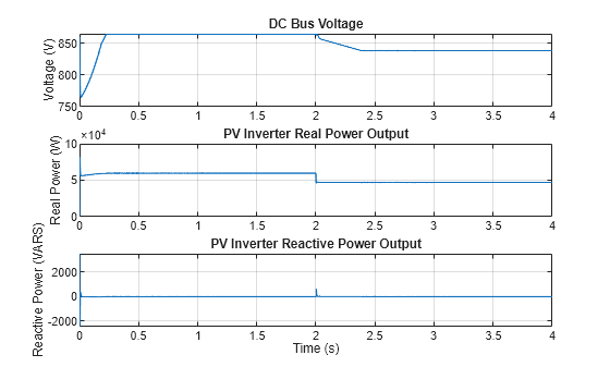
Control Three-Phase Solar Inverter
Control a three-phase single-stage solar photovoltaic (PV) inverter using a Solar PV Controller (Three-Phase) block. In a grid-connected PV plant, a PV controller extracts the maximum power from the solar array and feeds it to the grid. To extract the maximum available PV power, the controller uses a maximum power point tracking (MPPT) algorithm.

Photovoltaic Thermal (PV/T) Hybrid Solar Panel
Model a multi-domain power cogeneration system using Simscape, Simscape Electrical™, and Simscape Fluids™.

Mars Helicopter System-Level Design
Use Simscape™ Electrical™ to model a helicopter with coaxial rotors suitable to fly on Mars. This helicopter takes inspiration from Ingenuity, the robotic helicopter developed by NASA, which accomplished the first powered flight on another planet.

DC Fast Charging Station for Electric Vehicles with Solar Cogeneration
Models a DC fast charging station with solar cogeneration connected with the three battery packs of electric vehicles (EV).
Ports
Input
Conserving
Parameters
References
[1] Gow, J.A. and C.D. Manning. “Development of a Photovoltaic Array Model for Use in Power-Electronics Simulation Studies.” IEEE Proceedings of Electric Power Applications, Vol. 146, No. 2, 1999, pp. 193–200.