Modeling System Architecture of Small UAV
Overview
This example shows how to use System Composer™ to set up the architecture for a small unmanned aerial vehicle, composed of six top-level components. Learn how to refine your architecture design by authoring interfaces, inspect linked textual requirements, define profiles and stereotypes, and run a static analysis on such an architecture model.
openProject("scExampleSmallUAV");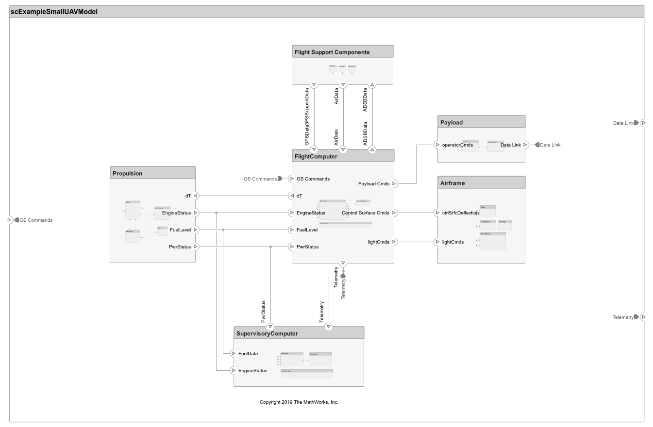
Each top-level component is decomposed into its subcomponents. Navigate through the hierarchy to view the composition for each component. The root component, scExampleSmallUAVModel, has input and output ports that represent data exchange between the system and its environment.
Author Interfaces
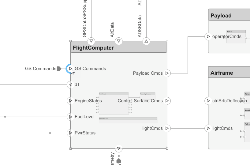
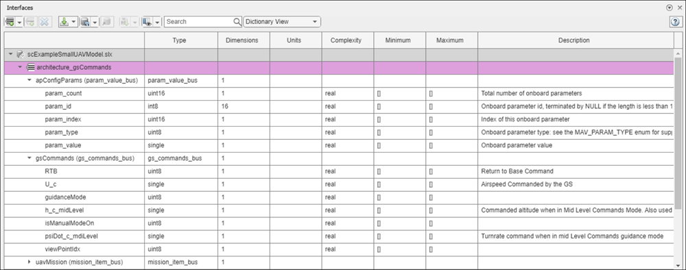
Define interfaces for domain-specific data between connections. The information shared between two ports defined by interface element property values further enhances the specification. To open the Interface Editor, in the Modeling tab in the toolstrip, click Interface Editor.
Click the GS Commands port on the architecture model to highlight the architecture_gsCommands interface and indicate the assignment of the interface.
Inspect Requirements
A Requirements Toolbox™ license is required to inspect requirements in a System Composer architecture model.
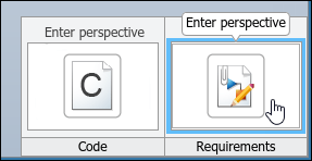
Components in the architecture model link to system requirements defined in scExampleSmallUAVModel.slreqx. Open the Requirements Manager (Requirements Toolbox). In the bottom right corner of the model pane, click Show Perspectives views. Then, click Requirements.
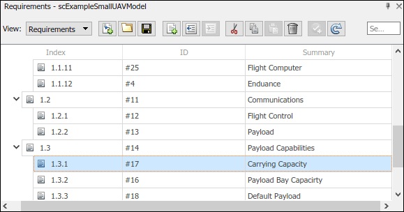
Select components on the model to see the requirement they link to, or, conversely, select items in the Requirements view to see which components implement them. Requirements can also be linked to connectors or ports to allow traceability throughout your design artifacts. To edit the requirements in smallUAVReqs.slreqx, select the Requirements Editor (Requirements Toolbox) from the menu.
The Carrying Capacity requirement highlights the total mass able to be carried by the aircraft. This requirement, along with the weight of the aircraft, is part of the mass roll-up analysis performed for early verification and validation.
Define Profiles and Stereotypes
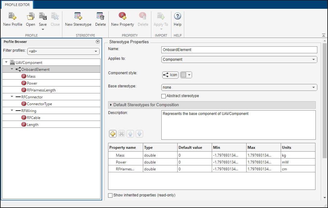
To complete specifications and enable analysis later in the design process, stereotypes add custom metadata to architecture model elements. This model has stereotypes for these elements:
On-board element, applicable to components
RF connector, applicable to ports
RF wiring, applicable to connectors
Stereotypes are defined in XML files by using profiles. The profile UAVComponent.xml is attached to this model. Edit a profile by using the Profile Editor. On the Modeling tab, click Profile Editor.
The display appears below.
Analyze the Model
To run static analyses on your system, create an analysis model from your architecture model. An analysis model is a tree of instances generated from the elements of the architecture model in which all referenced models are flattened out, and all variants are resolved.
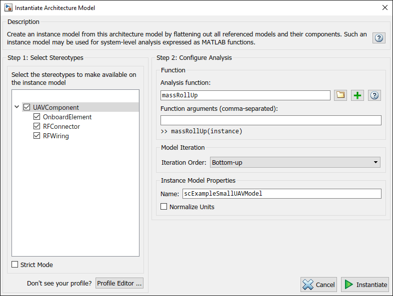
To open the Instantiate Architecture Model tool, click Analysis Model on the Views menu.
Run a mass roll-up on this model. In the dialog box, select the stereotypes that you want to include in your analysis. Select the analysis function by browsing to utilities/massRollUp.m. Set the model iteration mode to Bottom-up.
Uncheck Strict Mode so that all components can have a Mass property instantiated to facilitate calculation of total mass. Click Instantiate to generate an analysis.
Once on the Analysis Viewer screen, click Analyze. The analysis function iterates through model elements bottom up, assigning the Mass property of each component as a sum of the Mass properties of its subcomponents. The overall weight of the system is assigned to the Mass property of the top level component, scExampleSmallUAVModel.
See Also
setInterface | createProfile | addStereotype | addProperty | applyStereotype | instantiate
Topics
- Define Port Interfaces Between Components
- Allocate and Trace Requirements from Design to Verification
- Extend System Composer Language Elements Using Profiles
- Analyze Architecture
- Organize System Composer Files in Projects
- Validate Requirements for Machine Cooling System Architecture
- System Composer Concepts