Model Multirate Systems in Simulink with DSP System Toolbox
Learn how to model multirate systems in Simulink® using DSP System Toolbox™. Multirate systems can be found in a variety of different applications such as wireless, radar, audio, and consumer electronics.
A common challenge when downsampling or upsampling a signal is distortion. DSP System Toolbox provides a variety of multirate blocks that have built-in anti-aliasing and anti-imaging filters to prevent this distortion.
The DSP System toolbox can also be used to design and implement multirate multistage filters. Enter the filter specifications into the Filter Builder app, which then automatically determines the best algorithm for the desired filter response.
Published: 26 Jul 2022
Signal processing systems, which involves signals with more than one sampling rate are called multirate systems. In this video, we look at the potential advantages multirate systems offer and how to model and simulate them using Simulink and the DSP System Toolbox.
Multirate systems are found in a variety of different applications, such as wireless communication, RADAR and tracking, and consumer electronics, to name a few. Let's look at a simple example of a multirate system.
Here is a Simulink model where we want to combine two audio files recorded at different rates. The drums were recorded at 48 kilohertz, whereas the guitars were recorded at 44.1 kilohertz. The two rates can be visualized in Simulink by the signal lines of different colors. We combine the signals with an Add block and run the model.
[BUZZING]
The output is a jumbled audio, as the sample rates of the input signals to the add block don't match up. To combine them in a meaningful manner, we will need to convert the signals to a common frequency. Before we do that, let's cover a few basic concepts related to signal rate conversion.
Reducing the sampling rate of the signal is called downsampling. One of the biggest challenges when down sampling as signal is aliasing. Aliasing occurs due to the misrepresentation of the high-frequency components of a signal. And this may lead to distortion. Let's look at the frequency domain where this is easier to visualize.
If the spectrum of our signal is X omega, when we sample the signal, we effectively get copies of that spectrum. Then, when we downsample, the effect in the frequency domain is that the spectrum is stretched, and they shift closer together. At a certain rate, these spectral copies will start to overlap causing aliasing. To prevent this, a low-pass filter is used to cut off the high-frequency components. This is an anti-aliasing filter and is often used before downsampling.
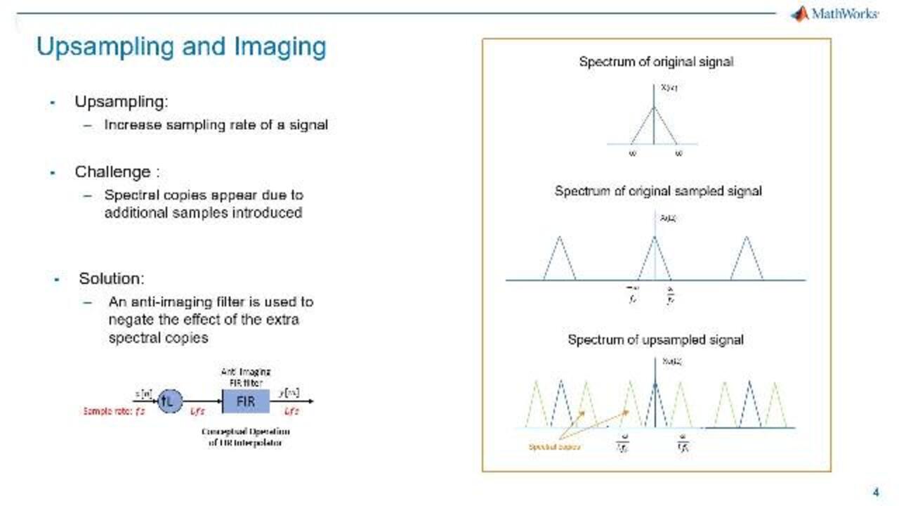
A different problem occurs when upsampling, where we insert samples, thus, increasing the sampling rate of a signal. Here, spectral copies appear due to the additional samples introduced. An anti-imaging filter then needs to be applied after upsampling to negate the effect of these extra spectral copies and in order to reconstruct the original signal faithfully.
Note that Simulink provides a variety of rate-conversion blocks, but a few are changing the sampling rate of a signal that carries nontrivial information, be sure to use the rate conversion blocks under the DSP System Toolbox Block Library. These blocks have built-in anti-aliasing and anti-imaging filters to avoid the distortion effects we saw earlier. Let's go back to our audio example in Simulink and use the FIR rate conversion block.
Let's insert the block to downsample to 48 kilohertz signal to the 44.1 kilohertz. Under the block parameters, we entered the ratio required and allow for multirate processing. Let's run the model.
[MUSIC PLAYING]
Great. That is what we were expecting. Notice now that the signals into the add block are both running at the same rate. In this case, the decimation factor required was 0.9. But what if we need to rate-convert a signal by a much higher factor? Let's look at a communication channel where this is needed.
Here's a simple block diagram. At the transmitter, the data is first modulated into a message signal, which is then upconverted orders of magnitude higher for transmission over an AWGN channel. And then, at the receiver, the signal has shifted back to its original frequency. The rate conversion factor required, in this case, is 64.
We could execute this rate conversion using a single filter block, but that would mean implementing a very large filter, which would be expensive to build. Instead, we use a series of smaller filters to achieve the same rate conversion. Let's look at this in detail using a Simulink model where we can create a working simulation of this block diagram. Here's the model in Simulink.
Under the transmitter subsystem is a series of three filters that we need, each with the rate-conversion factor of 4. The filter block lets you view the implementation costs of the filter. We can view this by clicking on the View Filter Response and the Filter Information button. If we compare this to a single filter of order 64, we see that the number of multipliers and adders required would be significantly higher than the combination of three smaller filters.
To summarize, we covered upsampling and downsampling in an audio system where we needed to combine data recorded at different rates. We did that by using multirate filter blocks from the DSP System Toolbox Block Library. Remember, these blocks have built-in anti-aliasing and anti-imaging filters for reliable signal-rate conversion.
We then looked at a multirate system in a communications channel where implementing a series of smaller filters helped reduce the overall implementation costs. To design multi-stage filters like this one, use the Filter Builder app. This app lets you enter filter specifications and then automatically finds the best algorithm for the desired response.
For more information about designing and implementing multirate and multistage filters in the DSP System Toolbox, please visit our documentation.
Related Products
Learn More

Featured Product
DSP System Toolbox


Select a Web Site
Choose a web site to get translated content where available and see local events and offers. Based on your location, we recommend that you select: United States.
You can also select a web site from the following list
Americas
- América Latina (Español)
- Canada (English)
- United States (English)
Europe
- Belgium (English)
- Denmark (English)
- Deutschland (Deutsch)
- España (Español)
- Finland (English)
- France (Français)
- Ireland (English)
- Italia (Italiano)
- Luxembourg (English)
- Netherlands (English)
- Norway (English)
- Österreich (Deutsch)
- Portugal (English)
- Sweden (English)
- Switzerland
- United Kingdom (English)