balunCoupledLine
Description
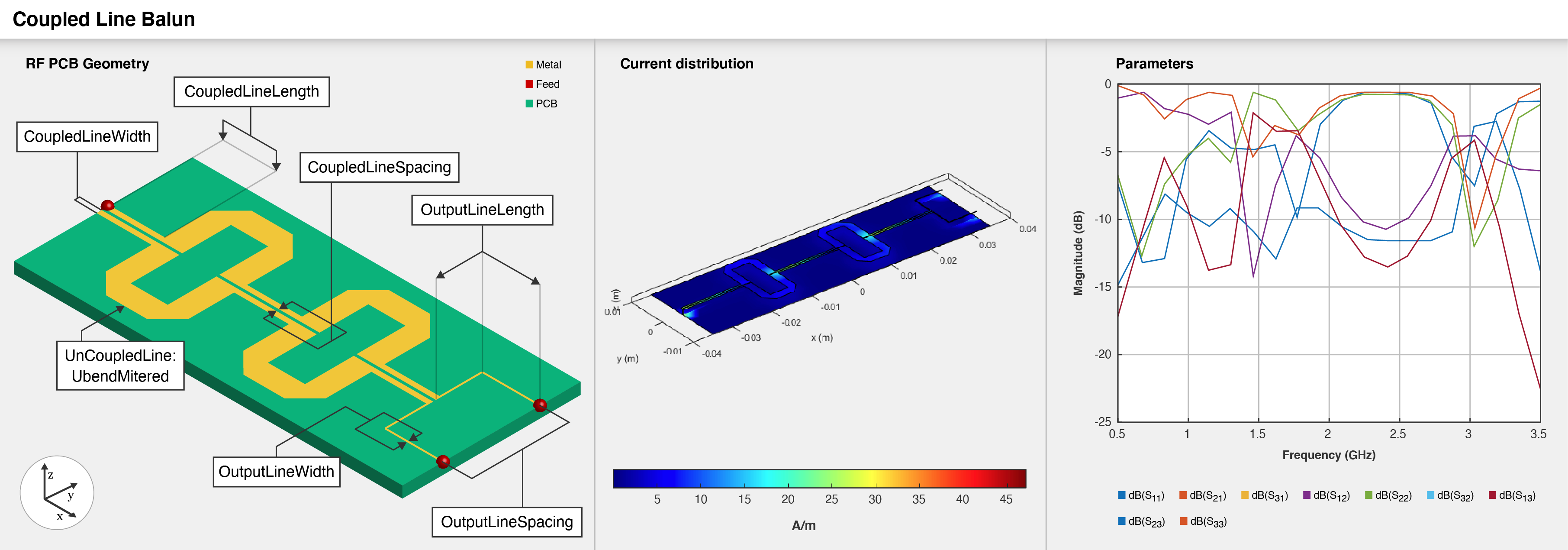
Use the balunCoupledLine object to create a multisection
coupled-line balun with an unbalanced input and a balanced output. The output signal has a
phase difference of 180 degrees.
Creation
Description
balun = balunCoupledLine creates a coupled-line balun in the
microstrip form with default properties for a resonant frequency of 2.96 GHz.
balun = balunCoupledLine(
sets Properties using one or more
name-value arguments. For example,
PropertyName=Value)balunCoupledLine(OutputLineLength=0.0286) creates a coupled-line
balun with an output line length of 0.0286 meters. Properties not specified retain their
default values.
Properties
Object Functions
charge | Calculate and plot charge distribution |
current | Calculate and plot current distribution |
designCoupledLine | Calculate dimensions of coupled-line section for specified frequency |
designUncoupledLine | Calculate dimensions of uncoupled-line section for specified frequency |
designOutputLine | Calculate dimensions of output line section for specified frequency |
feedCurrent | Calculate current at feed port |
layout | Plot all metal layers and board shape |
mesh | Change and view mesh properties of metal or dielectric in PCB component |
shapes | Extract all metal layer shapes of PCB component |
show | Display PCB component structure or PCB shape |
sparameters | Calculate S-parameters for RF PCB objects |
optimize | Optimize pcb catalog object |
EHfields | Electric and magnetic fields of PCB components |
Examples
Create a coupled-line balun using default properties.
balun = balunCoupledLine
balun =
  balunCoupledLine with properties:

    NumCoupledLineSection: 3
        CoupledLineLength: 0.0153
         CoupledLineWidth: 4.0000e-04
       CoupledLineSpacing: 1.4000e-04
       UncoupledLineShape: [1×1 ubendMitered]
         OutputLineLength: 0.0124
          OutputLineWidth: 1.5300e-04
        OutputLineSpacing: 0.0110
                   Height: 0.0013
         GroundPlaneWidth: 0.0200
                Substrate: [1×1 dielectric]
                Conductor: [1×1 metal]
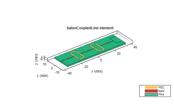
Visualize the coupled-line balun.
show(balun)
Create a coupled-line balun using default properties.
balun = balunCoupledLine;
Change the substrate and the dielectric of the balun.
balun.Substrate = dielectric('Name',{'Teflon','Teflon'},'EpsilonR', ...
    [2.1 2.1],'LossTangent',[0 0],'Thickness',[0.8e-3 0.8e-3]);
balun.Height = 0.8e-3;
Visualize the balun.
show(balun)

Create a coupled-line balun with an OutputLineSpacing of 5 mm.
balun = balunCoupledLine('OutputLineSpacing',0.005);Visualize the balun.
show(balun);

Define the frequency at 4 GHz.
f = 4e9;
Create a coupled line balun object.
balun = balunCoupledLine
balun =
  balunCoupledLine with properties:

    NumCoupledLineSection: 3
        CoupledLineLength: 0.0153
         CoupledLineWidth: 4.0000e-04
       CoupledLineSpacing: 1.4000e-04
       UncoupledLineShape: [1×1 ubendMitered]
         OutputLineLength: 0.0124
          OutputLineWidth: 1.5300e-04
        OutputLineSpacing: 0.0110
                   Height: 0.0013
         GroundPlaneWidth: 0.0200
                Substrate: [1×1 dielectric]
                Conductor: [1×1 metal]
show(balun)

Step 1: Design coupled line section
Design the coupled line section of the balun with an even mode impedance of 159 ohms and an odd mode impedance of 51 ohms. Use the helper function designCoupledLine.
[ClineL,ClineW,ClineS] = designCoupledLine(balun,f,'Z0e',159,'Z0o',51)
ClineL =
0.0107
ClineW =
4.2682e-04
ClineS =
1.4374e-04
Step 2: Design uncoupled line section
Design the uncoupled line section of the balun with the even and odd mode impedance of 59 ohms. Use the helper function designUncoupledLine.
[unclineL,unclineW] = designUncoupledLine(balun,f,'Z0',59,'LineLength',0.25)
unclineL =
0.0103
unclineW =
0.0018
Step 3: Design output line section
Design the output line section of the balun at the same frequency to extend the port 2 and port3. Use the helper function designOutputLine.
[OutL,OutW] = designOutputLine(balun,f,'Z0e',159,'Z0o',51,'Z0',59,'Zref',50)
OutL =
0.0109
OutW =
1.6115e-04
Set all the design dimensions to the coupled balun object.
balun.CoupledLineLength  = ClineL;
balun.CoupledLineWidth  = ClineW;
balun.CoupledLineSpacing  = ClineS;
UnCoupledLine = ubendMitered;
UnCoupledLine.Length  = [unclineL/2,unclineL/4,unclineL/2];
UnCoupledLine.Width   = [unclineW,unclineW,unclineW];
balun.UncoupledLineShape = UnCoupledLine;
balun.OutputLineLength = OutL;
balun.OutputLineWidth = OutW;
balun.OutputLineSpacing = OutL+ClineS;
gndW = 25e-3;
balun.GroundPlaneWidth = gndW;
show(balun)

Analyze and plot the S-parameters of this balun.
s11 = sparameters(balun,linspace(3.5e9,4.5e9,31));

figure; rfplot(s11,1,1);
hold on; rfplot(s11,1,3)
hold on; rfplot(s11,1,2)

References
[1] Pozar, David M. Microwave Engineering. 4th ed. Hoboken, NJ: Wiley, 2012.
Version History
Introduced in R2022a