Define Custom Pynq-Z2 Board with SoC Blockset
This example shows how to define the TUL Pynq-Z2 board as a custom board in SoC Blockset™, that supports the same features as the off-the-shelf SoC Blockset boards.
Introduction
SoC Blockset supports a set of SoC and FPGA boards. To support custom boards, such as a board with different DDR memory or I/O devices, SoC Blockset provides general APIs. This example shows how to use these APIs to implement support for the TUL Pynq-Z2 board.
Typical workflow to add custom board support follows these steps:
Collect board information, which may include certain source files.
Specify board information using board support APIs.
Save board information into hardware information files.
Use Prebuilt Linux Image
For convenience, this example includes a prebuilt Linux® image. You can download the customized Linux image for the Pynq-Z2 board and skip the next section. After downloading, extract the .img file from the .gz archive.
Customize Linux Image
To customize the Linux image for the Pynq-Z2 board, follow the instructions in the Customize PetaLinux Image for AMD Xilinx Devices example, using the meta-mathworks Yocto layer on GitHub.
Generate the Pynq-Z2 board support package (BSP) as shown in the Xilinx PYNQ repository.
Use the information in the README.md on GitHub to set up the host Linux desktop with the required software.
Use the following commands in the host Linux desktop to download the repository and create the BSP.
% cd /home/user && git clone git@github.com:Xilinx/PYNQ -b v3.0.1
% cd /home/user && git clone git@github.com:mathworks/meta-mathworks -b petalinux-v2022.1
% source /opt/petalinux/2022.1/settings.sh
% cd /home/user/PYNQ/sdbuild && make bsp BOARDS=Pynq-Z2
% cd /home/user/PYNQ/sdbuild/build/Pynq-Z2/petalinux_bsp
% petalinux-config
Run the petalinux-config command, and add the user Layers /home/user/PYNQ/sdbuild/boot/meta-pynq and /home/user/meta-mathworks.
Create Board Support
Collect Hardware Board Information
Get information about the GPIO, clock, reset, JTAG chain position, and memory size in the board user guide. Then implement the processing system using Vivado® software and verify the functionality:
Extract the TCL and constraint files from the processing system design. These files are used to generate the FPGA bitstream.
You can create the processing system TCL file by creating an empty project in Vivado® with the Zynq-7000™ settings and by extracting processing system parts from the block design TCL script.
For convenience this example includes a TCL file,
PynqZ2PS.tcl.
Get Linux Device Tree Information
The device tree blob (DTB) is generated from the device tree information.
Use the
defineBoardSupportFilesfunction in thecreateCustomPynqZ2Boardscript to specify the device-tree source files.Specify the hardware board information and features using the board support API as done in
createCustomPynqZ2Board. Run the following MATLAB® function to implement the board support.
boardSupportObj = createCustomPynqZ2Board;
Set up third-party software tools by running the following MATLAB command. The board support can use the same software tools as the reference board support, in this case
Board Support for Xilinx Zynq-7000 SoC.
soc.sdk.setupSoftwareTools('TUL Pynq-Z2');
Save the current MATLAB path if you want to use the board in different MATLAB sessions.
Boot Linux Image
Write Linux Image to a Micro SD card
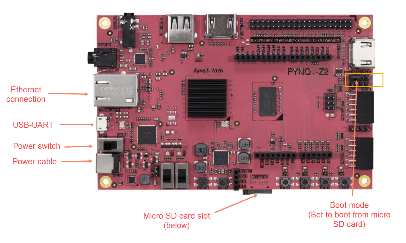
Pynq-Z2 board boots from a Linux image installed on a micro SD card.
Use image writer software like Win32DiskImager from SourceForge or Balena Etcher on Windows® to write the Linux image to your micro SD card.
If you are using a Linux desktop, you can use Linux
ddcommand to write to the micro SD card:
% sudo dd if=pynq-z2-2022-1.img of=/dev/sdX status=progress # /dev/sdX is your SD Card device name
Board Connection and Power-on

Insert the micro SD card into the Pynq-Z2 SD card slot.
Connect the power-supply.
Connect the USB-UART port of the Pynq-Z2 board to your computer using a micro USB cable.
Turn on the board.
Open the serial terminal on the board using PuTTy or TeraTerm software.
Set Up Network
From the serial terminal, open the
/etc/network/interfacesfile on the board.Set the appropriate settings for
eth0network interface.Reboot the board.
Use Board Support
Now you can use the new hardware board, TUL Pynq-Z2, with SoC Blockset. For example, you can use this board to implement the Streaming Data from Hardware to Software example. To try the example, open the top model soc_hwsw_stream_top. On the System on Chip tab, click Hardware Settings. In the Configuration Parameters dialog box, on the Hardware Implementation tab, select TUL Pynq-Z2 in Hardware board.

The hardware board settings are constrained according to values specified in createCustomPynqZ2Board. For example, under Target hardware resources > FPGA design (mem controllers), the Controller data width (bits) parameter is set to 64.

The parameter was defined by the following line in createCustomPynqZ2Board.
procSysObj.SlaveInterfaceDataWidth = 64;
You can now follow the instructions in the Streaming Data from Hardware to Software example to simulate and deploy your model on the Pynq-Z2 board. This video shows the Streaming Data from Hardware to Software running on the Pynq-Z2 board.

Distribute Board Support
If you want to share the new board support, you can package the board support as a MATLAB toolbox. For more information on MATLAB toolboxes, see Create and Share Toolboxes. Run the following command in MATLAB to generate the MLTBX file.
soc.sdk.packageBoardSupport('Board Support for Pynq-Z2');
The MLTBX file is located in the board support folder. It contains the information you provided in the previous section, including any source files.
Install Board Support
To install the board support on another computer, follow these steps:
From the MATLAB Current Folder pane, click the MLTBX file created in the previous step. The MLTBX file creates the board support folder in the MATLAB Add-Ons folder, extracts the board support files, and adds the required folders to the MATLAB path.
Register the new board support with SoC Blockset by running the following MATLAB command.
sl_refresh_customizations;
Set up third-party software tools by running the following MATLAB command.
soc.sdk.packageBoardSupport('Board Support for Pynq-Z2');
Other Things to Try
Apply the same workflow to add support for different boards if they are based on the same device family. For pure FPGA applications, you can also add the support for the board without processor cores.