How to generate multiple output in Simulink with multiple input
Show older comments
Recently, in order to get more familiar with simulink, I tried to establish some easy simulink model(figure shown in the following), however, there is a wierd bug. I inserted a sine wave with different amplitude, equivalently, two inputs into the matlab function block. Intuitively, this testbench should gives two output, but my workspace window only showed one ! so I want to consult what kind of consideration that I miss, thanks for you guys answer this question!(attatched file is the code of function block )
Answers (1)
Vidhi Agarwal
on 17 Jul 2025
0 votes
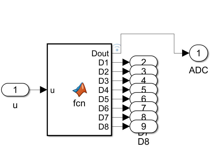
The diagram represents a Simulink model (possibly for digital signal processing or embedded systems simulation). Here’s a step-by-step explanation:
- Input ('u'): The model receives an input signal labeled as 'u' (with a value of 1 in this instance).
- MATLAB Function Block ('fcn'): The input 'u' is fed into a MATLAB Function block, which processes the input using a custom function ('fcn'). The function block outputs 8 digital signals labeled as `D1` to `D8` (collectively `Dout`).
- Digital Output Ports ('D1' to 'D8'): Each output from the function block is routed to a corresponding digital output port (numbered 2 to 9).
- ADC Block: The outputs from the digital ports are then combined and fed into an ADC (Analog-to-Digital Converter) block. The ADC output is labeled as '1'.
This model demonstrates the process of converting an analog signal into digital form using MATLAB/Simulink and visualizes the individual digital bits.
Categories
Find more on Sources in Help Center and File Exchange
on 17 Jul 2025
Community Treasure Hunt
Find the treasures in MATLAB Central and discover how the community can help you!
Start Hunting!