Thermal Modeling and Control Design for CPU Chip Cooling System
Overview
This four-part tutorial shows a workflow that you can use to take a high-fidelity physical model of a single component all the way through a fully integrated control system design process. This process is helpful when you are working on a model-based design process in a cross-functional engineering team, and the model fidelity requirement is different across the domains. For example, the high level of accuracy captured by the full-fidelity finite element model may not be needed in system level design, therefore you can create a reduced-order model for faster simulations.
Design Workflow
To model the system and perform the control design, follow these steps.
Create a finite element model of heat sink and extract matrices for state-space model simulation — Use Partial Differential Equation Toolbox™ software to develop a thermal finite element model of a heat sink. Then, you use the
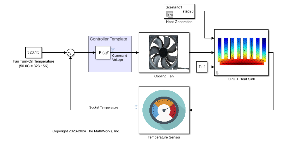
assembleFEMatrices(Partial Differential Equation Toolbox) function to extract the finite element formulation matrices you can use to create a descriptor state-space model. For more information, see Create Heat Sink Finite Element Model and Export Data for State-Space Simulation.Import finite element model data into Simulink® — Export a system of finite element matrix equations and use them for state-space model simulation using the Descriptor State-Space (Simulink) block. This example describes how to model the control system using four components: controller, actuation using a ducted fan, plant dynamics, and a sensor with first order delay. To validate this design, you also obtain a reduced order model for faster simulation. For more information, see Import Finite Element Model Data to Simulink.
Linearize the CPU and heat sink model and obtain reduced order model — Use tools available in Control System Toolbox™ and Simulink Control Design™ software to obtain a low-order linear parameter-varying (LPV) model. To do so, you linearize the CPU and heat sink block for seven values of fan speed, use balanced truncation to reduce the resulting sparse models, and combine the reduced models into an LPV model using the LPV System block. The resulting LPV model has an identical response as the full-fidelity CPU and heat sink model with very fast simulation time. For more information, see Create Low-Order LPV Model of CPU and Heat Sink Model.
Tune PI controller to obtain the desired response from the control loop — Use the low-order LPV model to tune a PI controller for the closed loop model. The controller drive the fan and keeps the temperature at a desired limit. This example also shows various scenarios and design techniques you can use with PI controller to obtain the desired response. For more information, see Tune PI Controller for Heat Sink Model.
See Also
Blocks
- LPV System | Descriptor State-Space (Simulink) | PID Controller (Simulink)
Functions
femodel(Partial Differential Equation Toolbox) |assembleFEMatrices(Partial Differential Equation Toolbox) |linearize(Simulink Control Design) |reducespec|pidtune