spiralEquiangular
Create equiangular spiral antenna
Description
The default spiralEquiangular object is a planar equiangular spiral
antenna on the xy- plane resonating around 4.15 GHz. The equiangular
spiral is always center fed and has two arms. The field characteristics of the antenna
are frequency independent. A realizable spiral has finite limits on the feeding region
and the outermost point of any arm of the spiral. This antenna exhibits a broadband
behavior. The outer radius imposes the low frequency limit and the inner radius imposes
the high frequency limit. The arm radius grows linearly as a function of the winding
angle. As a result, outer arms of the spiral are shaped to minimize
reflections.
The equation of the equiangular spiral is:
, where:
r0 is the starting radius
a is the growth rate
ϕ is the winding angle of the spiral

Creation
Description
se = spiralEquiangular
se = spiralEquiangular(PropertyName=Value)PropertyName is the property name
and Value is the corresponding value. You can specify
several name-value arguments in any order as
PropertyName1=Value1,...,PropertyNameN=ValueN.
Properties that you do not specify, retain their default values.
For example, se =
spiralEquiangular(WindingDirection="CW") creates a planar
equiangular spiral with windings spread in clockwise direction.
Properties
Object Functions
axialRatio | Calculate and plot axial ratio of antenna or array |
bandwidth | Calculate and plot absolute bandwidth of antenna or array |
beamwidth | Beamwidth of antenna |
charge | Charge distribution on antenna or array surface |
current | Current distribution on antenna or array surface |
design | Create antenna, array, or AI-based antenna resonating at specified frequency |
efficiency | Calculate and plot radiation efficiency of antenna or array |
EHfields | Electric and magnetic fields of antennas or embedded electric and magnetic fields of antenna element in arrays |
feedCurrent | Calculate current at feed for antenna or array |
impedance | Calculate and plot input impedance of antenna or scan impedance of array |
info | Display information about antenna, array, or platform |
memoryEstimate | Estimate memory required to solve antenna or array mesh |
mesh | Generate and view mesh for antennas, arrays, and custom shapes |
meshconfig | Change meshing mode of antenna, array, custom antenna, custom array, or custom geometry |
msiwrite | Write antenna or array analysis data to MSI planet file |
optimize | Optimize antenna and array catalog elements using SADEA or TR-SADEA algorithm |
pattern | Plot radiation pattern of antenna, array, or embedded element of array |
patternAzimuth | Azimuth plane radiation pattern of antenna or array |
patternElevation | Elevation plane radiation pattern of antenna or array |
peakRadiation | Calculate and mark maximum radiation points of antenna or array on radiation pattern |
rcs | Calculate and plot monostatic and bistatic radar cross section (RCS) of platform, antenna, or array |
resonantFrequency | Calculate and plot resonant frequency of antenna |
returnLoss | Calculate and plot return loss of antenna or scan return loss of array |
show | Display antenna, array, AI-based antenna, platform, or shape |
sparameters | Calculate S-parameters for antenna or array |
stlwrite | Write mesh information to STL file |
vswr | Calculate and plot voltage standing wave ratio (VSWR) of antenna or array element |
Examples
Create and view an equiangular spiral antenna with 0.35 growth rate, 0.65 mm inner radius and 40 mm outer radius.
se = spiralEquiangular(GrowthRate=0.35,InnerRadius=0.65e-3,...
    OuterRadius=40e-3);
show(se)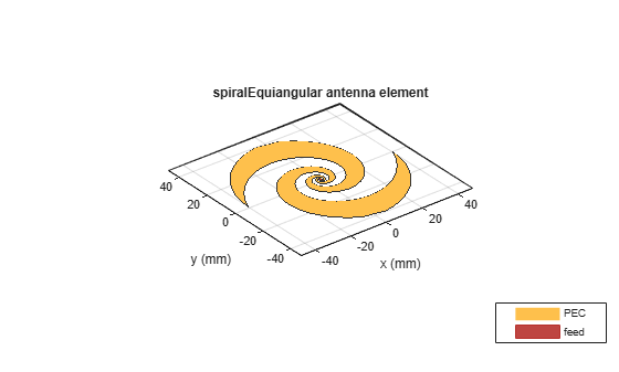
Plot the radiation pattern of equiangular spiral at a frequency of 4 GHz.
se = spiralEquiangular(GrowthRate=0.35,InnerRadius=0.65e-3,...
    OuterRadius=40e-3);
pattern(se,4e9);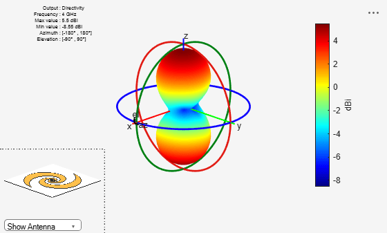
References
[1] Dyson, J. The equiangular spiral antenna.” IRE Transactions on Antennas and Propagation. Vol.7, Number 2, pp. 181, 187, April 1959.
[2] Nakano, H., K.Kikkawa, N.Kondo, Y.Iitsuka, J.Yamauchi. “Low-Profile Equiangular Spiral Antenna Backed by an EBG Reflector.” IRE Transactions on Antennas and Propagation. Vol. 57, No. 25, May 2009, pp. 1309–1318.
[3] McFadden, M., and Scott, W.R. “Analysis of the Equiangular Spiral Antenna on a Dielectric Substrate.” IEEE Transactions on Antennas and Propagation. Vol. 55, No. 11, Nov. 2007, pp. 3163–3171.
[4] Violakis, John Antenna Engineering Handbook, 4th Ed., McGraw-Hill.
Version History
Introduced in R2015a